

Views: 0 Author: Site Editor Publish Time: 2026-07-10 Origin: Site


Premature pavement failure costs municipalities and private developers millions of dollars annually. Improperly sizing geogrids leads directly to these catastrophic structural failures. You risk severe surface rutting and base shear when materials fail to confine the aggregate. Conversely, over-specifying grid parameters creates bloated project budgets and wastes valuable resources. We must move beyond basic product definitions to solve this issue. This guide provides a practical, evidence-based framework for specifying the correct material. You will learn to determine exact grid parameters based on subgrade strength, aggregate size, and load requirements. Standard manufacturer specification sheets typically represent ideal laboratory conditions. Real-world applications demand a much more skeptical, evidence-based approach. You must apply accurate reduction factors to guarantee long-term stability. By mastering these variables, you ensure optimal pavement performance. You can confidently select a PP biaxial geogrid that matches your specific site conditions perfectly.
Road reinforcement relies entirely on the mechanical interaction between the geogrid and the surrounding soil. Sizing procedures cannot begin without establishing baseline geotechnical data. Engineers often make the mistake of selecting materials based on availability rather than site requirements. You must gather precise field measurements before finalizing any design parameters. Specifying a road reinforcement PP biaxial geogrid demands accurate subgrade analysis. Without this data, the reinforcement layer may fail to distribute vertical loads properly. This failure leads directly to aggregate mixing and structural base collapse.
The California Bearing Ratio serves as the primary metric for subgrade strength. You must define the threshold carefully before choosing your reinforcement materials. Soft subgrades typically present a CBR value of less than 3. These challenging soils require entirely different tensile properties compared to moderate subgrades. Moderate subgrades generally range from a CBR of 3 to 8. They provide better natural bearing capacity but still benefit from aggregate confinement.
Base thickness reduction calculations rely heavily on accurate soil testing. You must perform localized CBR testing along the entire road alignment. Regional soil estimates often mask isolated weak zones. These weak zones will cause localized pavement failures if left unaddressed. Always test the specific soils you will encounter during excavation. You can then determine the exact stabilization requirements.
Dynamic loading directly impacts the required stiffness of the grid. Equivalent Single Axle Loads (ESALs) quantify the anticipated traffic over the pavement design life. Standard passenger vehicles inflict minimal stress on the road base. Heavy freight trucks and industrial equipment generate massive dynamic forces. These forces push the aggregate laterally.
You must correlate these dynamic loads with the radial stiffness of the grid. High-traffic industrial access roads require significantly stiffer materials than residential streets. If you underestimate the ESALs, the reinforcement will deform under repeated stress. This deformation allows the aggregate base to spread. The pavement surface will inevitably crack and fail as a result.
Confinement serves as the primary stabilization mechanism in road construction. The aggregate particles must drop into the grid openings. They lock against the polymer ribs under compaction. This interlocking action restricts lateral movement under heavy wheel loads. The resulting composite layer acts as a rigid platform.
You must follow the standard sizing rule to achieve optimal mechanical interlock. The geogrid aperture should ideally measure 1.1 to 1.2 times the maximum nominal diameter of the base aggregate. If the aperture is too small, the stones will merely rest on top. This floating effect creates a slip plane and destroys structural integrity. If the aperture is too large, the stones will pass right through without interlocking.
Many procurement teams focus solely on Ultimate Tensile Strength. High UTS alone is a deeply flawed metric for road stabilization. Pavement structures fail long before the polymer reaches its breaking point. Road bases typically fail at very low strain levels. Emphasize the importance of tensile strength at 2% and 5% elongation instead.
When reviewing PP biaxial geogrid specifications, examine the low-strain modulus. A standard road reinforcement grid should provide robust strength at these low deformations. Typical requirements range from 20kN/m to 40kN/m depending on the ESALs. A grid that requires massive deformation to mobilize its strength offers no value to a rigid asphalt surface. The asphalt will crack before the grid engages.
The structural integrity of the nodes dictates the material's field performance. Nodes represent the points where the longitudinal and transverse ribs intersect. High junction efficiency prevents the grid from deforming under repeated multi-directional traffic loads. Wheel loads do not travel in perfectly straight lines. They exert radial, 360-degree stresses on the base layer.
If the nodes split or deform, the aperture shape distorts. The aggregate immediately loses confinement. You must verify that the junction efficiency exceeds 90% of the rib strength. This ensures the grid maintains its rigid geometric structure under intense pressure.
| Performance Metric | Relevance to Road Reinforcement | Target Specification Range |
|---|---|---|
| Aperture Size | Determines aggregate mechanical interlock. | 1.1x to 1.2x D50 aggregate size. |
| Tensile Strength @ 2% Strain | Controls early deformation and surface cracking. | Typically 7 to 14 kN/m. |
| Tensile Strength @ 5% Strain | Provides secondary structural confinement. | Typically 14 to 28 kN/m. |
| Junction Efficiency | Maintains grid geometry under radial loads. | > 90% of ultimate rib strength. |
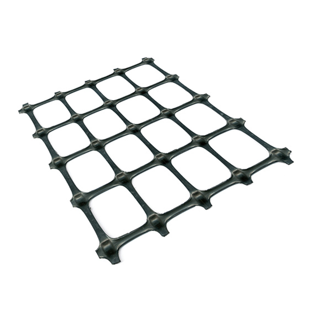
Engineers rely on established methodologies to validate their material choices. The Federal Highway Administration (FHWA) and AASHTO provide robust design protocols. The industry has slowly transitioned from unpaved structural models to comprehensive flexible pavement design protocols. You must understand how these models evaluate geosynthetic inclusions.
Avoid making specific engineering guarantees based on simplified charts. Instead, outline the accepted calculation frameworks used by authoritative bodies like Caltrans. These agencies utilize empirical data to determine base course reduction ratios. They evaluate how grid stiffness improves the structural number of the pavement section. This approach grounds your design in proven, peer-reviewed science.
Manufacturer datasheets advertise ultimate index properties. Real-world conditions degrade these properties significantly. You must apply Reduction Factors (RF) to calculate the Long-Term Design Strength (LTDS) of the material. Failing to account for these factors results in immediate over-engineering risks.
Grid sizing directly connects to overall project efficiency. You must calculate roll sizes accurately to prevent severe budget overruns. Subgrade softness dictates the required overlap width. Firm subgrades generally require a minimal overlap of 300mm. Very soft soils (CBR < 1) may demand overlaps up to 900mm.
This overlap requirement creates significant financial risk. Using standard roll widths on irregular road alignments increases waste exponentially. Every curved section requires cutting and overlapping to maintain structural continuity. You must calculate the net usable area of each roll. Do not simply divide the road square footage by the gross roll square footage. This common error leaves construction crews critically short on materials.
Installation survivability matters just as much as tensile strength. You must establish strict compaction tolerances for the construction crew. Detail the practical limits of heavy equipment operating over the grid. Never allow heavy tracked vehicles to drive directly on the exposed polymer fibers.
Establish a minimum lift thickness for the initial aggregate layer. A 150mm lift usually provides adequate protection before heavy rolling begins. This buffer zone prevents the steel drum from crushing the grid junctions against the hard subgrade. Proper compaction techniques preserve the mechanical interlock you specifically engineered the system to achieve.
Procurement teams face critical choices when ordering materials. You must identify when off-the-shelf sizes suffice. Standard 3.95m x 50m rolls work well for simple, straight access roads. They ship quickly and fit inside standard shipping containers easily. However, large highway projects present different logistical challenges.
Project scale often justifies ordering a custom PP biaxial geogrid to match specific lane widths. Custom widths eliminate continuous longitudinal overlaps. This strategy minimizes intensive manual labor and reduces material waste dramatically. You should calculate the labor savings against the potentially longer manufacturing lead time. Custom rolls streamline the installation process on massive commercial projects.
Selecting the right manufacturing partner protects your project from catastrophic material failures. Evaluating a PP biaxial geogrid supplier requires strict technical scrutiny. Do not base your decision on pricing alone. Establish rigid criteria for shortlisting potential manufacturing partners.
Always request third-party ISO testing data. You need independent verification of the claimed tensile properties. Ask for recent batch consistency reports to ensure manufacturing uniformity. Demand clear documentation calculating the long-term design strength (LTDS). Emphasize supply chain transparency. You must confirm realistic delivery lead times for bulk reinforcement projects to avoid costly site delays.
Specifying the correct reinforcement material requires a methodical, evidence-based approach. The optimal decision matrix combines accurate geotechnical data, precise aggregate matching, and true low-strain performance metrics. You cannot rely on ultimate tensile strength alone to stabilize a road base effectively. Prioritize junction efficiency and mechanical interlock to prevent aggregate lateral movement. Understand the realities of installation damage and calculate your overlaps meticulously. We strongly encourage engineers and procurement teams to share their site’s CBR and aggregate data with their technical sales rep. You should always run detailed base-course reduction calculations together before finalizing any purchase orders.
A: Temporary haul roads over moderate subgrades typically require standard 20x20 kN/m biaxial geogrids. They handle short-term, heavy dynamic loads effectively. Permanent highways facing high traffic volumes and strict settlement tolerances demand stiffer materials. You will typically specify 30x30 kN/m or 40x40 kN/m grids for these demanding, long-term applications.
A: You must calculate the maximum nominal diameter (D50) of your base aggregate. Multiply this aggregate dimension by 1.1 to 1.2. This formula determines the ideal aperture size. It guarantees the stones will drop into the grid and lock firmly against the polymer ribs.
A: No. High ultimate tensile strength is often a misleading metric. Road bases fail at very low deformations. Tensile stiffness at 2% and 5% strain matters significantly more. Additionally, high junction efficiency ensures the grid remains structurally stable under multi-directional wheel loads.
A: Yes. Many advanced manufacturers can adjust their production lines to create custom roll widths. This process perfectly matches your specific lane dimensions. However, custom manufacturing usually requires minimum order quantities and extended lead times. You must plan your procurement schedule accordingly.


