

Views: 0 Author: Site Editor Publish Time: 2026-07-15 Origin: Site


Incorrect geogrid specification causes catastrophic infrastructure failures. It triggers premature pavement rutting. It leads to collapsed embankments. Choosing between uniaxial and biaxial grids requires precise engineering logic. You cannot simply guess the right material. You must match the tensile strength vector directly to your infrastructure's specific load demands. We designed this guide for contractors, civil engineers, and project managers. You need an evidence-based evaluation framework before breaking ground. We will help you select the exact geosynthetic material required for your next build. You will learn how load direction influences performance. You will see how soil conditions dictate your polymer choice. We will explore how structural requirements define your grid selection. This knowledge prevents costly wall collapses. It eliminates dangerous road base failures. Read on to master the mechanics of proper geogrid specification.
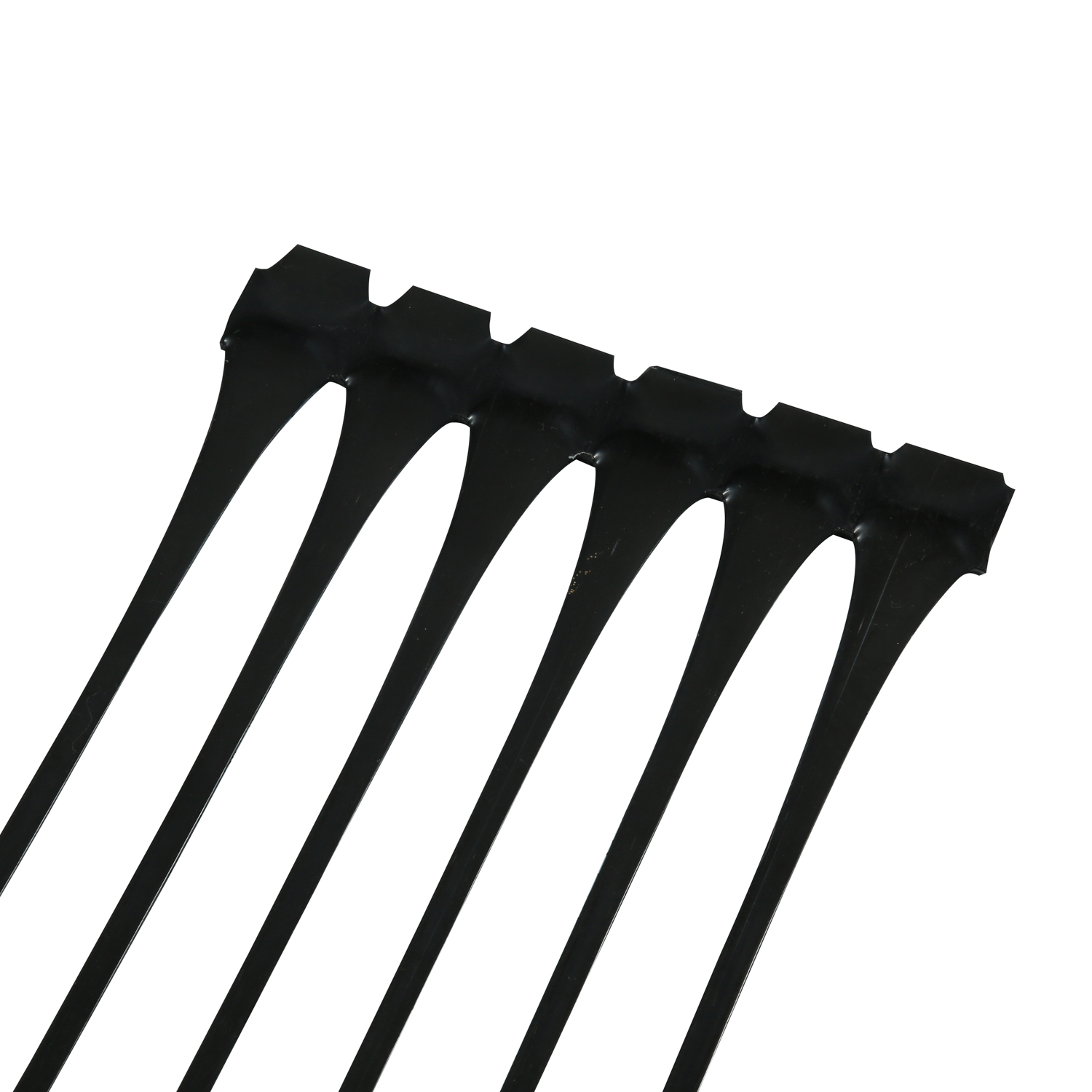
Uniaxial geogrids deliver maximum tensile strength in a single direction; they are mandatory for lateral load applications like retaining walls and steep slope reinforcement.
Biaxial geogrids distribute loads across two directions, making them the standard choice for base stabilization in roads and parking lots.
Material composition matters: PP (Polypropylene) is typically used for biaxial grids, while HDPE (High-Density Polyethylene) is standard for uniaxial due to its superior resistance to long-term creep.
Using the wrong grid—or installing a uniaxial grid in the wrong orientation—can lead to structural collapse or voided warranties.
You must understand basic soil physics to specify geosynthetics correctly. Soil handles compression beautifully. It supports massive vertical weights easily. However, soil entirely lacks tensile strength. It pulls apart rapidly under lateral stress. Geogrids provide this missing tension. They act like steel rebar inside concrete. They grab the surrounding soil. They hold it firmly together under intense pressure.
Engineers design uniaxial grids to resist continuous stress in one specific direction. We call this the machine direction. These grids feature long, narrow apertures. Manufacturers stretch the polymer heavily along a single axis during production. This unidirectional stretching aligns the molecular structure. It maximizes tensile strength along that single vector. You will typically rely on a uniaxial geogrid to hold back massive, directional earth loads.
Conversely, biaxial grids handle multi-directional stress. They feature square or rectangular apertures. Manufacturers stretch the polymer in both the machine and cross-machine directions. This creates a rigid framework. The square design interlocks tightly with angular aggregate. They confine base materials effectively across a horizontal plane.
Implementation reality presents major challenges on the job site. Visual identification matters immensely. Construction crews often make dangerous mistakes during installation. They might roll out the wrong grid because the black polymer rolls look similar. This common field error proves incredibly costly. You must train installation teams to spot the visual differences instantly. Narrow rectangles mean one-way strength. Perfect squares mean two-way strength. Failing to recognize this distinction leads directly to structural failure.
Chart: Uniaxial vs. Biaxial Core Mechanics Summary | ||
Feature | Uniaxial Geogrid | Biaxial Geogrid |
|---|---|---|
Primary Force Vector | Single direction (Lateral/Gravity) | Multi-directional (Vertical/Dynamic) |
Aperture Shape | Long, narrow rectangles | Square or nearly square |
Manufacturing Stretch | Machine Direction (MD) only | Machine (MD) and Cross-Machine (CMD) |
Core Function | Tie-back anchoring and soil tension | Aggregate interlock and lateral confinement |
The retaining wall challenge requires serious structural intervention. Earth behind a wall exerts massive lateral earth pressure. This pressure constantly wants to push the block face forward. Water infiltration magnifies this pressure significantly. Uniaxial grids act as vital tie-backs. They anchor the wall face deep into the compacted backfill. They safely transfer the outward load deep into the stable soil mass.
You must evaluate the necessity of a high-strength uniaxial retaining wall geogrid for larger structures. Standard gravity walls usually max out around three to four feet in height. Anything taller requires engineered reinforcement. The weight of the blocks alone cannot resist the soil wedge. A robust retaining wall reinforcement system prevents bulging, shifting, and catastrophic blowouts. The grid creates a massive stabilized soil block behind the fascia. This reinforced block acts as the true retaining structure.
We also rely heavily on these grids for specialized environmental stabilization. You will see numerous use cases for stabilizing steepened soil slopes. Embankments face constant attack from gravity. Gravity pulls material in a singular downward trajectory. Proper slope reinforcement stops landslides and controls erosion. It allows developers to build steeper slopes safely. This maximizes usable land area on tight commercial sites.
Experience shows us one specific installation error repeatedly. Roll orientation dictates the survival of your wall. Uniaxial grids must always run perpendicular to the wall face. The strong axis must extend backward into the compacted soil zone. Installing them parallel to the wall face provides absolutely zero structural reinforcement. The weak cross-machine direction cannot hold the earth pressure. This simple orientation mistake guarantees complete structural collapse.
Best Practice: Always cut uniaxial grids to the engineered length before placing them behind the wall.
Common Mistake: Rolling the grid left-to-right along the back of the blocks to save time.
Inspection Tip: Look at the ribs. The thick, continuous ribs must point straight back into the hill.
The pavement challenge differs entirely from retaining walls. Vehicular traffic creates intense dynamic loads. Heavy trucks impose multi-directional vertical stresses onto the road surface. These stresses travel downward and push the base aggregate outward. Pavements rapidly rut and crack without proper lateral confinement. Weak subgrades accelerate this deterioration.
Biaxial grids work through a precise mechanical process called lateral confinement. The aggregate pieces drop directly into the square apertures. Heavy rollers compact the stone. The angular rock locks tightly against the rigid plastic ribs. This interlocking mechanism completely changes the base layer's performance. It spreads the wheel load across a much wider subgrade area. We often compare this mechanism to wearing a snowshoe over deep, soft snow. The grid prevents the rock from punching down into the soft clay below.
You will specify biaxial reinforcement across several primary applications. We see them used extensively in unpaved logging or access roads. They reinforce paved municipal highways. They stabilize heavy-duty industrial yards handling shipping containers. They create reliable working platforms over soft, compressible soils. Crane pads and wind turbine access roads heavily depend on this stabilization.
Contractors closely monitor material efficiency on large civil projects. Biaxial grids offer immediate structural and material efficiency. They allow contractors to reduce aggregate base thickness significantly. You can often reduce the required stone depth by up to 30% to 40% while maintaining the same structural capacity. This massive aggregate reduction easily offsets the initial purchase price of the grid material. You spend less time trucking stone. You generate less heavy equipment emissions. You finish the subgrade preparation much faster.
Deep wheel ruts forming after minimal construction traffic.
Pumping soils where wet clay pushes up through the rock layer.
Alligator cracking on the asphalt surface just months after paving.
Understanding polymer chemistry separates average contractors from true experts. Why does the polymer choice dictate the application? Because different plastics react differently to tension, soil chemistry, and time. You cannot swap them blindly.
PP (Polypropylene) represents the absolute industry standard for extruded biaxial grids. It is quite rigid. It offers excellent junction strength where the ribs meet. This rigidity is vital for locking aggregate in place. Manufacturers stretch PP in two directions during extrusion. It performs exceptionally well in road bases and parking lot foundations.
HDPE (High-Density Polyethylene) serves a different structural master. It is highly resistant to biological degradation. It survives severe chemical attacks hidden deep in the soil. HDPE remains the undisputed gold standard for uniaxial grids. It possesses incredibly high tensile stiffness. More importantly, it resists "creep." Creep is the slow, permanent stretching of plastic under a constant, heavy load. A towering retaining wall applies constant stress 24 hours a day. HDPE refuses to stretch over decades of continuous pressure.
PET (Polyester) frequently appears in woven, flexible geogrids. Yarns of polyester are woven together and then coated. However, raw PET breaks down rapidly in highly alkaline environments. It requires a distinct, robust protective coating. Manufacturers usually apply a heavy PVC or polymer coating. This coating resists the highly alkaline conditions found near curing concrete blocks. You must ensure the coating remains fully intact during installation.
You need a strict decision lens for procurement. You must match the polymer directly to the site's environmental conditions. Check the soil's pH level in the geotechnical report. Consider the project's required design life. Commercial retaining walls usually demand a 75 to 100-year design life. Road bases might only target a 20-year cycle before repaving. Choosing a durable PP HDPE geogrid system guarantees optimal performance tailored exactly to these demanding lifespans.
Table: Polymer Properties Comparison | |||
Polymer Type | Primary Application | Key Strength | Environmental Vulnerability |
|---|---|---|---|
PP (Polypropylene) | Biaxial / Roads | High junction rigidity | UV degradation if left exposed |
HDPE (High-Density Polyethylene) | Uniaxial / Walls | Extreme creep resistance | Difficult to manipulate in freezing weather |
PET (Polyester) | Woven / Mixed | High flexibility and strength | Alkaline degradation (requires PVC coating) |
Engineers and buyers must follow a rigid procurement framework. Skipping steps here leads to catastrophic field failures. We recommend a four-step evaluation process before placing any material orders.
Step 1: Identify the Primary Force Vector. You must visualize how the load interacts with the ground. Is gravity pushing a wall outward? That represents a single-direction lateral force. You need Uniaxial. Is a heavy truck driving overhead? That creates a 360-degree, multi-directional vertical force. You require Biaxial. This initial assessment narrows your product catalog instantly.
Step 2: Geotechnical Prerequisites. Do not specify tensile strength based on sheer guesswork. You must require a comprehensive soil report from a licensed engineer. You need to identify the soil's internal friction angle. You must measure soil cohesion. You need the compacted unit weight. These three numbers dictate exactly how much tension your specific soil reinforcement grid must provide.
Step 3: Review Technical Data Sheets (TDS). Look closely beyond the marketed Ultimate Tensile Strength. Ultimate strength only measures the force required to snap the grid in a laboratory. It ignores long-term field realities. You must evaluate the Long-Term Design Strength (LTDS). You must calculate Creep Reduction Factors. You also need to factor in Installation Damage. Sharp aggregate dropping from a loader bucket damages plastic ribs. The TDS must account for this inevitable job site damage.
Step 4: Compliance & Certifications. Verify the manufacturer’s rigorous testing data. It must comply strictly with recognized ASTM standards. Look for ASTM D6637 when evaluating tensile properties. Look for ASTM D5262 for long-term creep behavior. Check your local Department of Transportation (DOT) regulations. Many public works projects require materials sourced only from pre-approved manufacturer lists.
The uniaxial versus biaxial debate remains strictly an application debate. You do not choose one because it is inherently better. You choose the one engineered for your specific physics problem. Uniaxial builds towering walls. Biaxial builds resilient roads. They perform fundamentally different mechanical jobs based on aperture shape and polymer stretching.
We strongly advise you to consult with a licensed geotechnical engineer before your next earthwork phase. They will calculate your exact lateral and vertical load requirements safely. Always prompt them to request comprehensive technical data sheets. Obtain a project-specific quote and installation guidelines from a fully certified manufacturer to guarantee long-term infrastructural success.
A: It is highly discouraged and economically inefficient. Biaxial grids lack the concentrated, single-direction tensile strength required to safely anchor heavy lateral earth loads. They stretch too much under sustained one-way pressure, leading to wall bulging or catastrophic failure.
A: Typically every 2 to 3 courses of block (16 to 24 inches), but this must be dictated by a site-specific engineered design. Taller walls, poor soil conditions, or heavy surcharge loads at the top will require closer spacing and longer grid lengths.
A: Yes. For subgrade stabilization over weak soils, you place it directly at the subgrade and base interface. For base reinforcement to reduce aggregate thickness, you may place it within the middle of the crushed aggregate layer. Depth changes the interlocking efficiency.
A: When properly specified and installed completely away from ultraviolet (UV) exposure, modern polymer geogrids are highly inert. They resist chemicals and biological breakdown. They routinely achieve engineered design lives exceeding 75 to 100 years in typical soil pH conditions.


